 SuZhou Tonkida Electromechanical Technology Co., Ltd
Professional SMT whole line supplier
SuZhou Tonkida Electromechanical Technology Co., Ltd
Professional SMT whole line supplier

SuZhou Tonkida Electromechanical Technology Co., Ltd
Pho:13913521916
Tel:0512-65637950
Fax:0512-65637950
Add:No. 6 Tengqi Street, Wuzhong District, Suzhou City, Jiangsu Province, China
Now:Home>>News>>Company news
Classification:Company news Release time:2023-05-14 892 hits
one. Clean the work platform frequently ...
one. Clean the work platform frequently (once per shift, some lost CHIP components should be cleaned in time).
2. Fill lubricating oil on time, and check whether the moving part is lacking lubricating oil from time to time.
3. Check the grounding status of the machine every week to ensure normal power supply.
4. Check the gas supply status of the machine every week to ensure a good air source (the air source should be added with a filter device to filter water and oil).
5. Timely maintenance according to the maintenance plan provided by the equipment manufacturer can ensure that your machine is in good condition.
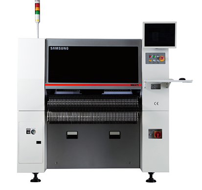
Take HS94796L as an example
HSP4796L is mainly mounted chip components, using a group of 16 rotating chip heads, each chip head has 5 kinds of nozzle, double feeding platform, each feeding platform can be installed more than 80 kinds of components (8mm), the chip speed 0.10s/ piece, can be mounted 0201-20mm size chips, etc.
2 Common fault analysis and elimination
2.1 Component absorbing error
Components from the high-speed motion of the sticker head, removed from the packaging tape, affixed to the printed board in the process, will produce not taken, lost after absorption and other poor absorption failures, these failures will cause a large number of component losses, according to our experience, component absorption is usually caused by the following reasons:
(1) The vacuum negative pressure is insufficient, when the suction nozzle takes the element, the suction nozzle produces a certain negative pressure, the element is adsorbed on the suction mouth, and the negative pressure detection method is generally used to determine whether the suction nozzle picks up the element is abnormal. When the negative pressure sensor detects the value within a certain range, the machine thinks that the absorption is normal, and the other way is that the absorption is poor. When the component is absorbed, the vacuum negative pressure should be above 53.33kPa, so that there is enough vacuum to absorb the component. If the vacuum negative pressure is insufficient, it will not be able to provide enough suction elements, in use, we should often check the vacuum negative pressure, and regularly clean the nozzle, but also pay attention to the pollution of the vacuum filter element of each mounting head, its role is to filter the air source that reaches the nozzle, and replace the black pollution to ensure the smooth flow of air.
(2) Nozzle wear, nozzle deformation, blockage, damage caused by insufficient air pressure, resulting in suction components, so it is necessary to regularly check the degree of wear of the nozzle, serious replacement.
(3) The influence of the feeder, poor feeding of the feeder (the feeder gear is damaged), the material belt hole is not stuck on the feeder gear, there are foreign bodies under the feeder and the spring wear), the compression belt cover plate, spring and other operating mechanisms cause deformation, rust, etc., resulting in component bias, vertical or unable to absorb the device, so it should be checked regularly and dealt with in time when problems are found. So as not to cause a lot of waste of devices.
(4) The influence of the height of absorption, the ideal height of absorption is to press down 0.05mm when the nozzle touches the surface of the component, if the depth of the pressure is too large, it will cause the component to be pressed in the feed tank but can not take the material. If the absorption of a component is not good, the absorption height can be adjusted slightly upward, such as 0.05mm. In the actual work process, the author has encountered a bad suction of all components on a platform, and the solution is to appropriately move up the extraction height of the platform in the system parameters.
(5) Incoming material problems, some manufacturers produce chip component packaging quality problems, such as the hole spacing error is large, the adhesive force between the paper tape and the plastic film is too large, the size of the tank is too small, etc., are the possible reasons for the components can not be picked up.
2.2 Component identification error
The visual inspection system of HSP4796L is composed of two parts, component thickness detection system and optical recognition system, so the analysis of identification errors should start from these two aspects.
(1) Component thickness detection error, component thickness detection is through the linear sensor installed on the mechanism, to detect the side of the device, and compared with the thickness value set in the component library, can determine the bad suction state of the component (vertical, side suction, oblique suction, leakage suction, etc.), when the thickness value set in the component library and the measured value exceeds the allowable error range, There will be poor thickness detection, resulting in component loss, so it is important to correctly set the component thickness in the component library, and often clean the linear sensor to prevent dust, debris, oil, etc. attached to it from affecting the thickness of the device and the detection of the absorption state.
(2) Component visual detection error, the optical recognition system is fixed in an elevation CCD camera system, it is in the rotation of the mounting head through the camera to identify the outline of the component and optical imaging, while the central position and rotation Angle of the device relative to the camera is measured and recorded, transmitted to the drive control system, Thus the x, y coordinate position deviation and θ Angle deviation compensation, its advantage lies in the flexibility and can be applied to various specifications and shapes of the device. It has two types of backlight recognition and front light recognition. The front light recognition is based on the component lead, the recognition accuracy is not affected by the size of the nozzle, and the electrode position of the device can be clearly detected. Even if the pin is hidden in the shape of the component, the device PLCC, SOJ, etc., can be accurately mounted, and the backlight recognition is based on the shape of the component. It is mainly used to identify chip resistance-capacitance components and triodes, etc., and the recognition accuracy will be affected by the size of the nozzle.
Possible causes of component visual inspection errors are:
1) Influence of the nozzle. When backlight recognition is adopted, if the shape of the nozzle is larger than the profile of the device, there will be the profile of the nozzle in the image, as shown in Figure 3. The recognition system will regard the profile of the nozzle as a part of the component, thus affecting the identification alignment of the component. The solution depends on the specific situation:
a, if the outside diameter of the nozzle is larger than the device size, change the nozzle with a smaller outside diameter.
b, suction nozzle position deviation causes the shape of the nozzle to extend to the device profile, adjust the material level deviation. HSP4796L has the function of automatic correction of the suction position of components. By continuously measuring the suction position of a component, the average error is calculated and the correction value is automatically generated to compensate. The correction value is stored in the Feeder (B) Offest, and the automatic correction value generated for each material level is stored in the database. The problem can be solved by clearing the deviation value of the material level where the component is located to zero.
2) Improper setting of component library parameters. This is usually due to the refueling component shape is inconsistent caused by the need to re-check the identification parameters set, check items include component shape and size, etc. An effective solution is to let the visual system "learn" the component shape, the system will generate a CAD similar comprehensive description, this method is fast and effective, and if the size of the incoming material is not consistent, The tolerance can be appropriately increased.
3) The influence of the aperture light source, the intensity of the light source will gradually decrease after the use of the aperture light source for a long period of time, because the intensity of the light source is proportional to the gray value of the solid-state camera conversion, and the larger the gray value is, the closer the digital image is to the view observed by people, so with the reduction of the intensity of the light source, the gray value will also decrease accordingly. However, the grayscale value in the machine will not decrease with the reduction of the intensity of the light source, only the regular correction detection, the grayscale value will be proportional to the intensity of the light source, when the intensity of the light source is weakened to the point that it cannot identify the component, the bulb needs to be replaced.
4) The impact of the reflector, the reflector only works on the backlight, when there is dust on the reflector, the intensity of the light source of the camera is reduced when reflected, and the gray value is small, which is prone to poor identification, resulting in component loss, and the reflector is a component that needs to be wiped regularly.
5) The influence of foreign bodies on the lens, there is a glass lens above the aperture, its role is to prevent dust from entering the aperture, affecting the intensity of the light source, but if there are dust, components and other foreign bodies on the glass lens, it also affects the intensity of the light source, the light source intensity is low, and the gray value is low. This is also easy to lead to poor identification, the patch machine should pay attention to the cleaning of the lens and various lenses.
2.3 Flying Parts
The flying parts refer to the loss of components in the patch position, and the main reasons are as follows:
(1) The component thickness is set incorrectly, if the component thickness is thin, but the database is set thicker, then the nozzle will be put down when the component has not reached the pad position, and the x-y table that fixes the PCB is moving at high speed, resulting in flying parts due to inertia. So set the component thickness correctly.
(2) The PCB thickness is set wrong, if the actual thickness of the PCB is thin, but the database is set thicker, then the support pin will not be able to completely lift the PCB during the production process, and the component may be put down before reaching the pad position, resulting in flying parts.
(3) PCB reasons, there are usually several reasons:
1) PCB itself, PCB warping exceeds the allowable error of the equipment, general requirements are shown in Table 1.
2) Support pin placement problem. When making a double-sided mount PCB, when making the second side, the support pin is top on the bottom component of the PCB, causing the PCB to warp upward, or the support pin is not evenly placed, and some parts of the PCB are not top up, resulting in the PCB cannot be completely jacked up

Hotline
13913521916
Add:No. 6 Tengqi Street, Wuzhong District, Suzhou City, Jiangsu Province, China
Pho:0512-65637950
All rights reserved:SuZhou Tonkida Electromechanical Technology Co., Ltd
备案号:苏ICP备16061850号-1 苏公网安备 32050602010620号
SuZhou Tonkida Electromechanical Technology Co., Ltd Main business三星贴片机,韩华贴片机,SMT贴片机,是韩国三星授权的三星贴片机,韩华贴片机代理经销商及服务商.欢迎来电咨询!xml地图 htm地图 txt地图